Search FAQs
High Supply Temp Shutdown Installation on a NetworkAIR FM
Issue:
High Supply Temp Shutdown Installation on a NetworkAIR FM
Product line:
FM
Environment:
Data Center Cooling
Cause:
Resolution:
The Remote Power-Off [RPO] feature enables you to turn off functionality to the NetworkAir FM. This is not an Emergency Power-Off feature or Kill Switch. Power will not be stopped only the applicable modes will be stopped, causing the unit to become idle. Please use an Emergency Power-Off [EPO] system for complete protection in emergencies
Step1: User Interface Set-up
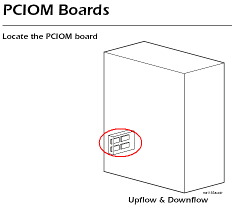
1. The Molex plugs need to be wired accordingly below. This board below is called the Programmable Customer Input/Output Module (PCIOM). The PCIOM can be found in the User Interface Box, which is located near the bottom on the left of the FM. See screen shot below. The PCIOM allows you to set input contacts to cause alarm conditions based on their current state and a user-defined
normal state. Output contacts can map internal alarms and events to outside devices.

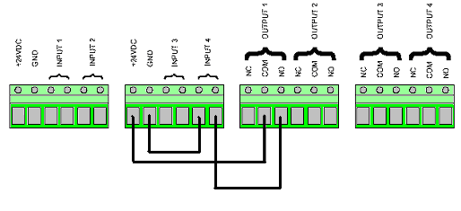
2. Once the PCIOM is found, land your wires as seen below.

3. From the main screen of the display use this path: Setup >> System >> Input/Output >> Input Contacts
A. Select Input: 4 of 4 (use enter then the down/up arrow to change the input number. Use Enter when the cursor is on the setting you would change, then the down/up arrow to make changes.)
B. Set the following Fields:
1. Name: Use this section to name the Input.
2. Normal: Use this section to change the normal conditions of the circuit to either NO or NC. For our purposes here we will use NO.
3. Status: This section shows what the correct state of the circuit is at that instance
4. Delay: Use this to adjust the time delay of the shutdown ...
6. All steps are complete
4. From the main screen of the display use this path: Setup >> System >> Input/Output >> Output Contacts
A. Select Output: 1 of 4 (use enter then the down/up arrow to change the input number. Use Enter when the cursor is on the setting you would change, then the down/up arrow to make changes.)
B. Set the following Fields:
1. Map: Change this field to System MAIN MODULE HIGH SUPPLY TEMP.
2. State: Enable this field
3. Normal: Change this field to Open
4. Status: This section shows what the correct state of the circuit is at that instance
5. Steps complete
5. From the main screen of the display use this path: Setup >> System >> Alarms >> Temp Thrshlds
1. Supply: Change the high and low threshold settings. These are the settings that will shut down the air conditioner.
NOTE: With the above setup there will be no alarms or logs that the unit has shut off due to high supply temp. Look for a high supply temp alarm. The only other way to tell the unit is off is through the status light and the green LED on the PCIOM.
NOTE: above is wired to input #4 (If you use a different input then replace the input number with the input you use)
NOTE: The above diagrams are wired to output #1 (If you use a different input then replace the input number with the input you use)
High Supply Temp Shutdown Installation on a NetworkAIR FM
Product line:
FM
Environment:
Data Center Cooling
Cause:
Resolution:
The Remote Power-Off [RPO] feature enables you to turn off functionality to the NetworkAir FM. This is not an Emergency Power-Off feature or Kill Switch. Power will not be stopped only the applicable modes will be stopped, causing the unit to become idle. Please use an Emergency Power-Off [EPO] system for complete protection in emergencies
Step1: User Interface Set-up
1. The Molex plugs need to be wired accordingly below. This board below is called the Programmable Customer Input/Output Module (PCIOM). The PCIOM can be found in the User Interface Box, which is located near the bottom on the left of the FM. See screen shot below. The PCIOM allows you to set input contacts to cause alarm conditions based on their current state and a user-defined
normal state. Output contacts can map internal alarms and events to outside devices.
2. Once the PCIOM is found, land your wires as seen below.
3. From the main screen of the display use this path: Setup >> System >> Input/Output >> Input Contacts
A. Select Input: 4 of 4 (use enter then the down/up arrow to change the input number. Use Enter when the cursor is on the setting you would change, then the down/up arrow to make changes.)
B. Set the following Fields:
1. Name: Use this section to name the Input.
2. Normal: Use this section to change the normal conditions of the circuit to either NO or NC. For our purposes here we will use NO.
3. Status: This section shows what the correct state of the circuit is at that instance
4. Delay: Use this to adjust the time delay of the shutdown ...
- NOTE: There is an initial non-adjustable delay of 5 seconds for the contact. Example: If the delay is set to 10 seconds, it will actually be 15 seconds before the shutdown.
6. All steps are complete
4. From the main screen of the display use this path: Setup >> System >> Input/Output >> Output Contacts
A. Select Output: 1 of 4 (use enter then the down/up arrow to change the input number. Use Enter when the cursor is on the setting you would change, then the down/up arrow to make changes.)
B. Set the following Fields:
1. Map: Change this field to System MAIN MODULE HIGH SUPPLY TEMP.
2. State: Enable this field
3. Normal: Change this field to Open
4. Status: This section shows what the correct state of the circuit is at that instance
5. Steps complete
5. From the main screen of the display use this path: Setup >> System >> Alarms >> Temp Thrshlds
1. Supply: Change the high and low threshold settings. These are the settings that will shut down the air conditioner.
- NOTE: Set the low threshold very low and the high above the cooling Setpoint plus the deadband and a exaggerated factor. The exaggerated factor is your safety factor. You do not want that too high as it may never go off. Also you do not want it too low as it may prematurely go off.
NOTE: With the above setup there will be no alarms or logs that the unit has shut off due to high supply temp. Look for a high supply temp alarm. The only other way to tell the unit is off is through the status light and the green LED on the PCIOM.
NOTE: above is wired to input #4 (If you use a different input then replace the input number with the input you use)
NOTE: The above diagrams are wired to output #1 (If you use a different input then replace the input number with the input you use)

