Search FAQs
MGE STS, Galaxy 4000, 5000 and Galaxy PW; Wiring information for EGX100 to any 66061-supported products
Issue:
Wiring information for EGX100 to any 66061-supported products
Product line
EGX100 and all products supported by 66061 – STS, Galaxy 3000, 4000, 5000 and Galaxy PW
Environment:
EGX100 and all products supported by 66061 – STS, Galaxy 3000, 4000, 5000 and Galaxy PW
Cause:
Wiring information for EGX100 to any 66061-supported products
Resolution:
The 66061 JBUS/Modbus card is configured for 9600, 8, N and 1. Slave address is 1 and wiring is 2-wire with no parity and termination. This assumes only one 66061 card or UPS or STS is connected to the enclosure but if more than one change as required. The JBUS/Modbus card has two female DB9 connectors. The DB9 on the right side of the card is RS232 for configuration. The left side DB9 connector is the RS485 connections that the EGX must be wired to.
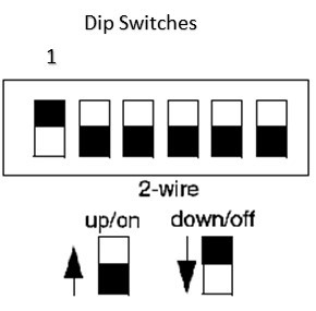
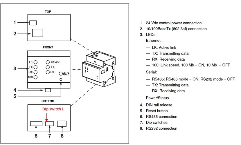
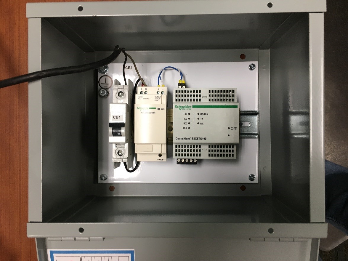
The EGX Monitoring Enclosure has a CB, power supply and EGX100. The EGX is configured and has been Modbus communications was factory tested. The EGX 100 IP address is 169.254.0.10 with subnet mask of 255.255.0.0. The IP address needs to be configured at the site. Make sure that the dip switches on the side of the EGX are configured correctly. One is down (off position) and all others are up.

EGX layout

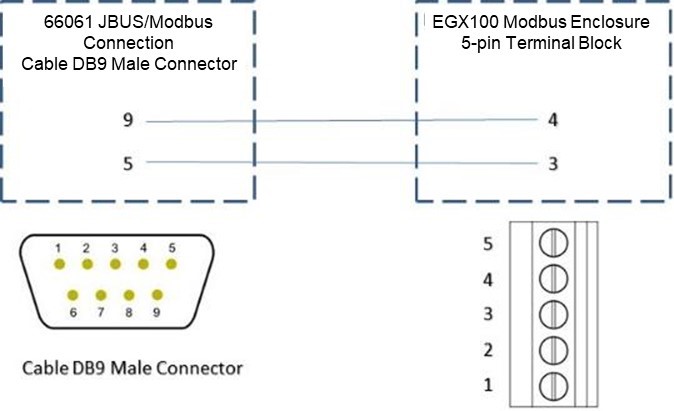
The wiring of the devices is below and keep in mind that the 66061 JBUS/Modbus card has a female DB9 so a male DB9 cable is required on the UPS/STS. The male DB9 connector is not supplied with the UPS but a black terminal block is supplied with the EGX.


Wiring information for EGX100 to any 66061-supported products
Product line
EGX100 and all products supported by 66061 – STS, Galaxy 3000, 4000, 5000 and Galaxy PW
Environment:
EGX100 and all products supported by 66061 – STS, Galaxy 3000, 4000, 5000 and Galaxy PW
Cause:
Wiring information for EGX100 to any 66061-supported products
Resolution:
The 66061 JBUS/Modbus card is configured for 9600, 8, N and 1. Slave address is 1 and wiring is 2-wire with no parity and termination. This assumes only one 66061 card or UPS or STS is connected to the enclosure but if more than one change as required. The JBUS/Modbus card has two female DB9 connectors. The DB9 on the right side of the card is RS232 for configuration. The left side DB9 connector is the RS485 connections that the EGX must be wired to.
The EGX Monitoring Enclosure has a CB, power supply and EGX100. The EGX is configured and has been Modbus communications was factory tested. The EGX 100 IP address is 169.254.0.10 with subnet mask of 255.255.0.0. The IP address needs to be configured at the site. Make sure that the dip switches on the side of the EGX are configured correctly. One is down (off position) and all others are up.
EGX layout
The wiring of the devices is below and keep in mind that the 66061 JBUS/Modbus card has a female DB9 so a male DB9 cable is required on the UPS/STS. The male DB9 connector is not supplied with the UPS but a black terminal block is supplied with the EGX.
Released for:APC Indonesia
Explore more

